Physical RAN
We are now ready to replace the emulated RAN with physical gNBs and
real UEs. You will need to edit hosts.ini to reflect the Aether
cluster you want to support, where just a single server is sufficient
and there is no reason to include nodes in the [gnbsim_nodes] set.
In addition to the server(s) in your cluster, bringing up a physical RAN requires the following hardware:
One or more 5G small cell radios (e.g., MOSO CANOPY 5G INDOOR SMALL CELL).
One or more 5G-capable UEs (e.g., unlocked Motorola Moto G 5G).
A SIM reader/writer and associated software (e.g., OYEITIMES MCR3516).
A set of programmable SIM cards (blank cards likely included with reader/writer).
There are multiple options for each component, but finding a combination that works together can be challenging. This section makes several recommendations based on working end-to-end systems. For simplicity, we pared the above list back to a single example for each item, but these should not be interpreted as the only possibility.
Note also that our example relies on the availability of spectrum in the CBRS band, which is available in the United States. Spectrum options are likely to be different in other countries.
Troubleshooting Hint
We are tracking community experience with different hardware in the
#aether-onramp channel of the ONF Workspace, with summaries of different
combinations people have tried reported in the OnRamp
Troubleshooting Wiki Page.
This blueprint assumes you start with a variant of vars/main.yml
customized for running physical 5G radios. This is easy to do:
$ cd vars
$ cp main-gNB.yml main.yml
This section focuses on bringing up a single gNB, and assumes that gNB
is on the same L2 network as the Aether cluster. In our running
example, this implies both are on subnet 10.76.28.0/24.
Troubleshooting Hint
Be aware that enterprise and campus networks have been known to filter packets in ways that impact gNB-to-Core connectivity. Fortunately, physical gNBs connect to SD-Core (both the AMF in the control plane and the UPF in the user plane) in exactly the same way as external instances of gNBsim. Going through the process of bringing up gNBsim in a second server, as described in the previous section, is a good way to validate that your Core is “gNB-ready”.
Modify Configuration
Modify the core section of vars/main.yml to match the
following, substituting your local details for ens18 and
10.76.28.113. Of particular note, setting ran_subnet to the
empty string indicates that the gNB is connected to the same physical
L2 network as your Aether cluster, and the new values_file is
tailored for a physical RAN rather than the emulated RAN we’ve been
using.
core:
    standalone: "true"
    data_iface: ens18
    values_file: "deps/5gc/roles/core/templates/radio-5g-values.yaml"
    ran_subnet: ""
    helm:
        chart_ref: aether/sd-core
        chart_version: 0.12.6
    upf:
        ip_prefix: "192.168.252.0/24"
    amf:
        ip: "10.76.28.113"
Prepare UEs
When selecting UEs to connect to Aether, be aware that not all phones support the CBRS frequency bands that Aether uses. For band n78, Aether is known to work with recent iPhones (11 and greater), Google Pixel phones (4 and greater), OnePlus phones, and Moto G 5G phones. For band n48, Aether is known to work with Moto G 5G and OnePlus phones; Pixel 7 phones are purported to work as well. Another option is to use a 5G dongle connected to a Raspberry Pi as a demonstration UE. This makes it easier to run diagnostic tests from the UE. For example, we have used APAL’s 5G dongle with Aether.
5G-connected devices must have a SIM card, which you are responsible
for programming and inserting. You will need a SIM card writer, such
as the OYEITIMES MCR3516 (available on Amazon), which comes with
five blank cards. You will need to set the PLMN identifier
(constructed from a valid MCC/MNC pair), the IMSI, and two secret keys
for each SIM card. As working examples, we have used two different
PLMN ids: 315010 constructed from MCC=315 (US) and MNC=010 (CBRS),
and 00101 constructed from MCC=001 (TEST) and MNC=01 (TEST). You
should use whatever values are appropriate for your local environment,
where we use the following as a running example throughout this
section:
IMSI: each one is unique, matching pattern
315010*********(up to 15 digits)OPc:
69d5c2eb2e2e624750541d3bbc692ba5Key:
000102030405060708090a0b0c0d0e0f
Note that the actual config files distributed with OnRamp have IMSIs
constructed using PLMN id 00101. Both sets of examples are taken
from working deployments (315010 for a 4G/eNB and 00101 for a
5G/gNB), so in principle either should work as a model you can emulate
in your deployment. As a practical matter, however, it is certainly
easiest (and safest) to start with the existing code.
After inserting the SIM card into the device and powering it up, log
into the phone, select Network Settings > SIMs and create a new
Access Point Name (APN), configured as shown in Figure 54. The entry name (TEST SIM in the example) is arbitrary
and the MCC/MNC pair is set automatically based on the newly inserted
SIM card. The important value is the APN, which is set to
internet. This value corresponds to variable dnn (Data
Network Name) defined in
deps/5gc/roles/core/templates/radio-5g-values.yaml. Loosely
speaking, the role the APN plays in the mobile network is similar to
the role an SSID plays in a WiFi network.
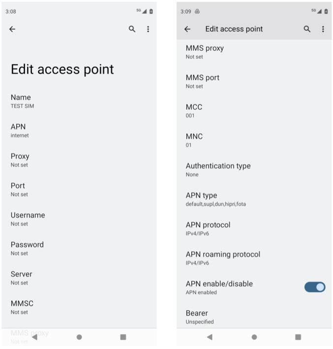
Figure 54. Configure an Access Point Name (APN) for the new SIM card on the UE.
Finally, modify the subscribers block of the
omec-sub-provision section in file
deps/5gc/roles/core/templates/radio-5g-values.yaml to record the IMSI,
OPc, and Key values configured onto your SIM cards. The block also
defines a sequence number that is intended to thwart replay
attacks. For example, the following code block adds IMSIs between
315010999912301 and 315010999912310:
subscribers:
- ueId-start: "315010999912301"
  ueId-end: "315010999912310"
  plmnId: "315010"
  opc: "69d5c2eb2e2e624750541d3bbc692ba5"
  key: "000102030405060708090a0b0c0d0e0f"
  sequenceNumber: 135
Further down in the same omec-sub-provision section you will find
two other blocks that also need to be edited. The first,
device-groups, assigns IMSIs to Device Groups. You will need to
reenter the individual IMSIs from the subscribers block that will
be part of the device-group:
device-groups:
- name:  "5g-user-group1"
   imsis:
       - "315010999912301"
       - "315010999912302"
       - "315010999912303"
The second block, network-slices, sets various parameters
associated with the Slices that connect device groups to
applications. Here, you will need to reenter the PLMN information,
with the other slice parameters remaining unchanged (for now):
plmn:
    mcc: "315"
    mnc: "010"
Aether supports multiple Device Groups and Slices, but the data
entered here is purposely minimal; it’s just enough to bring up and
debug the installation. Over the lifetime of a running system,
information about Device Groups and Slices (and the other
abstractions they build upon) should be entered via the ROC, as
described the section on Runtime Control. When you get to that point,
Ansible variable standalone in vars/main.yml (which
corresponds to the override value assigned to
provision-network-slice in radio-5g-values.yaml) should be set
to false. Doing so causes the device-groups and
network-slices blocks of radio-5g-values.yaml to be
ignored. The subscribers block is always required to configure
SD-Core.
Bring Up Aether
You are now ready to bring Aether on-line. We assume a fresh install by typing the following:
$ make aether-k8s-install
$ make aether-5gc-install
You can verify the installation by running kubectl just as you did
in earlier stages. Note that we postpone bringing up the AMP until
later so as to have fewer moving parts to debug.
gNodeB Setup
Once the SD-Core is up and running, we are ready to bring up the physical gNB. The details of how to do this depend on the specific device you are using, but we identify the main issues you need to address using SERCOMM’s 5G femto cell (as distributed by MosoLabs) as an example. That particular device uses either the n48 or n78 band and is on the ONF MarketPlace, where you can also find a User’s Guide that gives detailed instructions about configuring the gNB.
Further Reading
Troubleshooting Hint
The product data sheet shows support for frequency bands
n78/n48/n77, but individual devices do not necessarily support all
three. For example, we have experience with an n78 device and an n48
device, with the latter (n48) becoming the preferred band (due in
part to less risk of interfering with Radio Altimeters). For n48,
PLMN id 00101 is currently recommended.
For the purposes of the following description, we assume the gNB is
assigned IP address 10.76.28.187, which per our running example,
is on the same L2 network as our Aether server (10.76.28.113).
Figure 55 shows a screenshot of the SERCOMM
gNB management dashboard, which we reference in the instructions that
follow:
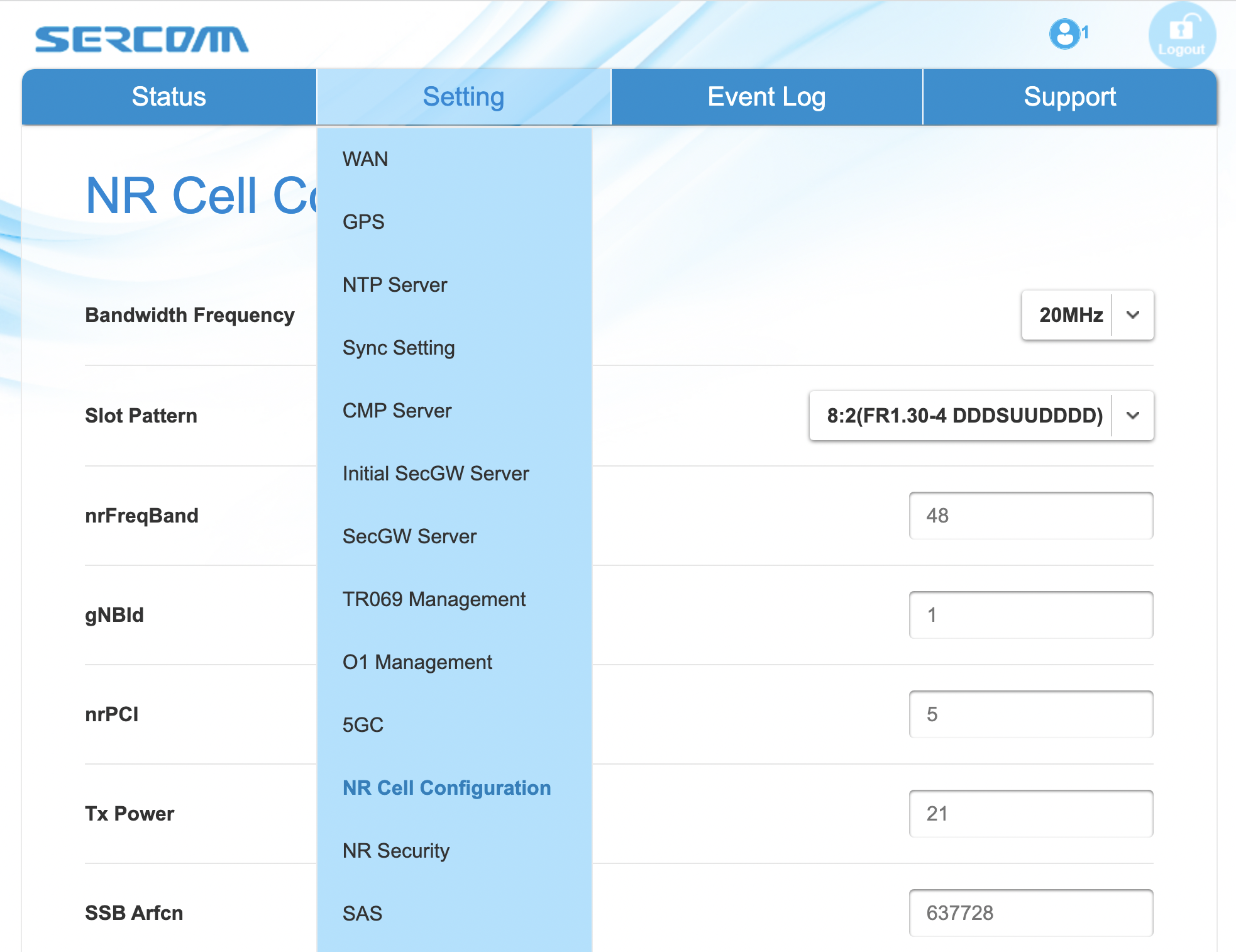
Figure 55. Management dashboard on the Sercomm gNB, showing the dropdown
Settings menu overlayed on the NR Cell Configuration page
(which shows default radio settings).
Connect to Management Interface. Start by connecting a laptop directly to the LAN port on the small cell, pointing your laptop’s web browser at the device’s management page (
https://10.10.10.189). You will need to assign your laptop an IP address on the same subnet (e.g.,10.10.10.100). Once connected, log in with the credentials provided by the vendor.Configure WAN. Visit the
Settings > WANpage to configure how the small cell connects to the Internet via its WAN port, either dynamically using DHCP or statically by setting the device’s IP address (10.76.28.187) and default gateway (10.76.28.1).Access Remote Management. Once on the Internet, it should be possible to reach the management dashboard without being directly connected to the LAN port (
https://10.76.28.187).Connect GPS. Connect the small cell’s GPS antenna to the GPS port, and place the antenna so it has line-of-site to the sky (i.e., place it in a window). The
Statuspage of the management dashboard should report its latitude, longitude, and fix time.Spectrum Access System. One reason the radio needs GPS is so it can report its location to a Spectrum Access System (SAS), a requirement in the US to coordinate access to the CBRS Spectrum in the 3.5 GHz band. For example, the production deployment of Aether uses the Google SAS portal, which the small cell can be configured to query periodically. To do so, visit the
Settings > SASpage. Acquiring the credentials needed to access the SAS requires you go through a certification process, but as a practical matter, it may be possible to test an isolated/low-power femto cell indoors before completing that process. Consult with your local network administrator.Configure Radio Parameters. Visit the
Settings > NR Cell
Configuration
page (shown in the figure) to set parameters that control the radio. It should be sufficient to use the default settings when getting started.Configure the PLMN. Visit the
Settings > 5GCpage to set the PLMN identifier on the small cell (00101) to match the MCC/MNC values (001/01) specified in the Core.Connect to Aether Control Plane. Also on the
Settings > 5GCpage, define the AMF Address to be the IP address of your Aether server (e.g.,10.76.28.113). Aether’s SD-Core is configured to expose the corresponding AMF via a well-known port, so the server’s IP address is sufficient to establish connectivity. TheStatuspage of the management dashboard should confirm that control interface is established.Connect to Aether User Plane. As described in an earlier section, the Aether User Plane (UPF) is running at IP address
192.168.252.3. Connecting to that address requires installing a route to subnet192.168.252.0/24. How you install this route is device and site-dependent. If the small cell provides a means to install static routes, then a route to destination192.168.252.0/24via gateway10.76.28.113(the server hosting Aether) will work. If the small cell does not allow static routes (as is the case for the SERCOMM gNB), then10.76.28.113can be installed as the default gateway, but doing so requires that your server also be configured to forward IP packets on to the Internet.
Troubleshooting Hint
For the SERCOMM gNB, if you elect to enable GPS, then Setting >
Sync_Settings > Sync_Mode should be set to TIME. With GPS and
PTP disabled, Setting > Sync_Settings > Sync_Mode should be set
to FREE_RUNNING.
Troubleshooting Hint
For the SERCOMM gNB, we recommend the following when the gNB’s addresses is acquired via DHCP, assuming that address is unlikely to change. When configuring the WAN (via the LAN), start with DHCP enabled. Note the IP address the gNB has been assigned, and then after disconnecting from the LAN, connect to the GUI via this address. You will be on the same L2 subnet as the Aether server, which you should be able to ping using the gNB’s diagnostic tool. The default gateway DHCP returns does not know how to route data packets to the UPF. To fix this, modify the WAN settings to use a static IP, with the DHCP-provided IP used as the gNB’s static address. Then set the default gateway to the IP address of your Aether server.
Run Diagnostics
Successfully connecting a UE to the Internet is not a straightforward exercise. It involves configuring the UE, gNB, and SD-Core software in a consistent way; establishing SCTP-based control plane (N2) and GTP-based user plane (N3) connections between the base station and Mobile Core; and traversing multiple IP subnets along the end-to-end path.
The UE and gNB provide limited diagnostic tools. For example, it’s
possible to run ping and traceroute from both. You can also
run the ksniff tool described in the Networking section, but the
most helpful packet traces you can capture are shown in the following
commands. You can run these on the Aether server, where we use our
example ens18 interface for illustrative purposes:
$ sudo tcpdump -i any sctp -w sctp-test.pcap
$ sudo tcpdump -i ens18 port 2152 -w gtp-outside.pcap
$ sudo tcpdump -i access port 2152 -w gtp-inside.pcap
$ sudo tcpdump -i core net 172.250.0.0/16 -w n6-inside.pcap
$ sudo tcpdump -i ens18 net 172.250.0.0/16 -w n6-outside.pcap
The first trace, saved in file sctp.pcap, captures SCTP packets
sent to establish the control path between the base station and the
Mobile Core (i.e., N2 messages). Toggling “Mobile Data” on the UE,
for example by turning Airplane Mode off and on, will generate the
relevant control plane traffic.
The second and third traces, saved in files gtp-outside.pcap and
gtp-inside.pcap, respectively, capture GTP packets (tunneled
through port 2152 ) on the RAN side of the UPF. Setting the
interface to ens18 corresponds to “outside” the UPF and setting
the interface to access corresponds to “inside” the UPF. Running
ping from the UE will generate the relevant user plane (N3) traffic.
Similarly, the fourth and fifth traces, saved in files
n6-inside.pcap and n6-outside.pcap, respectively, capture IP
packets on the Internet side of the UPF (which is known as the N6
interface in 3GPP). In these two tests, net 172.250.0.0/16
corresponds to the IP addresses assigned to UEs by the SMF. Running
ping from the UE will generate the relevant user plane traffic.
If the gtp-outside.pcap has packets and the gtp-inside.pcap
is empty (no packets captured), you may run the following commands
to make sure packets are forwarded from the ens18 interface
to the access interface and vice versa:
$ sudo iptables -A FORWARD -i ens18 -o access -j ACCEPT
$ sudo iptables -A FORWARD -i access -o ens18 -j ACCEPT
Support for eNBs
Aether OnRamp is geared towards 5G, but it does support physical eNBs,
including 4G-based versions of both SD-Core and AMP. It does not
support an emulated 4G RAN. The 4G blueprint uses all the same Ansible
machinery outlined in earlier sections, but starts with a variant of
vars/main.yml customized for running physical 4G radios:
$ cd vars
$ cp main-eNB.yml main.yml
Assuming that starting point, the following outlines the key differences from the 5G case:
There is a 4G-specific repo, which you can find in
deps/4gc.The
coresection ofvars/main.ymlspecifies a 4G-specific values file:values_file: "deps/4gc/roles/core/templates/radio-4g-values.yaml"The
ampsection ofvars/main.ymlspecifies that 4G-specific models and dashboards get loaded into the ROC and Monitoring services, respectively:roc_models: "deps/amp/roles/roc-load/templates/roc-4g-models.json"monitor_dashboard: "deps/amp/roles/monitor-load/templates/4g-monitor"You need to edit two files with details for the 4G SIM cards you use. One is the 4G-specific values file used to configure SD-Core:
deps/4gc/roles/core/templates/radio-4g-values.yamlThe other is the 4G-specific Models file used to bootstrap ROC:
deps/amp/roles/roc-load/templates/radio-4g-models.jsonThere are 4G-specific Make targets for SD-Core (e.g.,
make aether-4gc-installandmake aether-4gc-uninstall), but the Make targets for AMP (e.g.,make aether-amp-installandmake aether-amp-uninstall) work unchanged in both 4G and 5G.
The Quick Start and Emulated RAN (gNBsim) deployments are for 5G only, but revisiting the other sections—substituting the above for their 5G counterparts—serves as a guide for deploying a 4G version of Aether. Note that the network is configured in exactly the same way for both 4G and 5G. This is because SD-Core’s implementation of the UPF is used in both cases.